
Corrugating rollers several meters long emboss the wave form into the paper and glue it to the top layer. By using a cylindrical glue applicator roll, the glue is applied to the tips of the corrugated shape of the paper, which wraps around the corrugating roll. The tips touch the glue layer on the glue application roller, dip into the glue layer in a defined manner and take over a certain amount of glue for subsequent gluing. The quantity of glue picked up is adjusted by the distance between the glue application roller and the corrugating roller, the so-called glue gap.
")
Corrugating rolls with cylindrical measuring surface for distance measurement (roller gap)
High process temperature is required for adhesion between corrugated paper and the top layer and therefore the corrugating rolls are heated up to above 120°C for this purpose.
In order to guarantee a constant glue layer thickness, the roll spacing must be precisely controlled depending on many parameters, such as the rotation speed of the rolls or the type of used paper. If there is too much glue between the paper layers, the setting time is too long and if too little glue is applied, this can lead to only partial adhesion.

Cardboard with corrugated paper and cover layers
By using eddy current sensors, the roller spacing during production process is precisely measured and controlled by machine controller. For this purpose, two eddy current sensors are installed at the two roller ends for distance measurement and measure directly and contact-free on the cylindrical surface with micrometer accuracy and high dynamic response. By using two sensors at both roller ends, the angle error or the tilted position between the rollers is measured and corrected. In addition, the direct measurement on the rollers compensates the temperature expansion of the entire system. A measurement at the actuators of the rollers would be too inaccurate.
Especially for this application eddylab produces eddy current sensors which durably withstand high temperatures, vibrations and chemical pollution. The 2-channel driver electronics are mounted in a sealed aluminium housing with protection class IP68, so that cleaning cycles cannot harm the measuring system. The devices are manufactured at eddylab in Otterfing near Munich - Made in Germany.
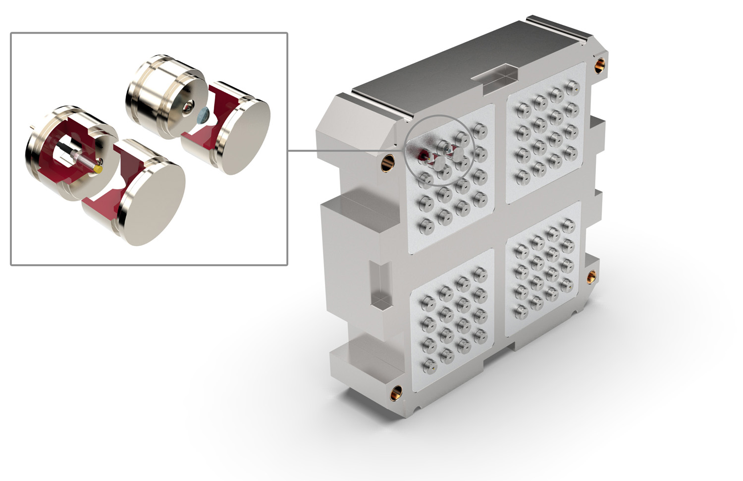
In test bench operation, the gearbox is exposed to all load conditions, which it should later withstand without damage during operation. This includes the lifetime test under normal conditions with parameters such as torque, engine speed, temperature and similar. The engineers also want to know how the transmission behaves under misuse loads, e.g. when shifting wrong gears at high speeds, slipping off the clutch pedal when starting at high engine speeds or the appearance of extreme torque peaks due to sudden changes in speed, such as when a rally car jumps over a hilltop. In contrast to normal operation, misuse loads result in extreme torque peaks exceeding many times the nominal torque of the engine. Excessive torque forces the main shaft and auxiliary shafts out of alignment, causing the shafts to bend. The bearing points are therefore subjected to damaging loads and, in extreme cases, permanent deformation or breakage can result.
During development of a gearbox, such extreme load conditions are taken into consideration and simulated by modern calculation methods. Later in the real test bench operation the simulation is verified with the experimental data. For this purpose it is necessary to install sensors in the gearbox at specific positions in order to measure all shaft movements in axial and radial direction. Preferably at the positions where the maximum movements are expected. Inductive probes based on the eddy current principle are the ideal sensors for this type of measurement, as they have an extremely high resolution and high dynamics at the same time. In addition, they can withstand the environmental conditions in the gearbox under oil, high temperatures and high vibrations as well as shock without any problems. The sensors have small dimensions and the temperature resistant PTFE cables are fed out of the gear unit and connected to the driver electronics for signal processing. This is located at a safe distance of several meters from the test object.
For determining the minimum distances of the probes to the measuring surfaces, the maximum values from the simulation results are used in order to avoid a collision between the probe head and the measuring surface. In the case of sinusoidal movements, the sensor heads must always be installed at a base distance according to half the measuring range. The largest misalignments are to be expected at the differential wheel. For the determination of the concentricity and the resulting eccentricity, 2 pcs. eddy current probes are arranged radially at an angle of 90 degrees. Two further probes are installed to measure the axial displacement of the differential wheel. The cables of the eddy current probes are fed through the differential cover oil-tight to the outside.

Gearbox view incl. eddy current probes (without differential cover)
For adaptation to the test bench and installation of the sensors on the differential wheel, a milled aluminium cover is used instead of the standard differential cover made of thin sheet metal to ensure vibration-free mounting of the sensors. All sensors can be easily installed in this aluminium cover and the entire arrangement can be mounted as a complete component group via the differential wheel for data acquisition. The eddy current probes are fixed in the probe mountings with a clamping pin for axial displacement and adjustment of the spacing.
 Differential cover with installed eddy current probes
The protruding shaft ends of the gearbox main and auxiliary shafts are equipped with a measuring kit to mount the probes. These probes are accessible from the outside and sealed with O-rings. To achieve a non-interrupted homogeneous surface for eddy current measurement, the gears are equipped with measuring sleeves for radial measurement and end plates for axial measurement.
 View of the gear shafts with complete installation of the eddy current probes
In addition to a base frame for increasing the distance and providing more space for the probes and brackets, the measuring kit contains two cylindrical probe brackets which are mounted in the gear housing via the various shaft ends. Each probe bracket has fixtures for two sensors, each arranged by 90 degrees, for measuring the radial displacement. The axial displacement of the gear shafts is measured with a probe mounted on each end face.

Measuring kit with probes, bracket, measuring surfaces and base frame
Modern turbochargers are highly complex systems. Actual design trend regarding the bearing of the turbo rotor is the use of ball bearings in combination with a squeeze film damper. The rotors in these machines are highly flexible shafts with double ball bearings and an additional damping oil layer (squeeze film) between the outer ring of the ball bearing and the turbocharger housing. The outer ring of the ball bearing is not fixed in the housing as usual. It can move radially in the oil layer similar to an oil-lubricated bush bearing with hydrodynamic lubricating wedge. The oscillation amplitude of the turbo rotor is damped. The shaft rotates at very high speed above 300,000 rpm. The rotor's natural resonance frequency is exceeded, i.e. the speed is supercritical and the turbo shaft rotates around its centre of gravity. As a result, the system dynamics are very complicated. In addition, unbalance and aerodynamic forces affect the turbine and compressor wheel and hydrodynamic forces are generated in the turbocharger bearings.

Eddy current probes measure the position of turbo rotor with squeeze film
For the design of the gap width of a squeeze film damper, it is important to measure actual displacement and vibration amplitudes of the turbo rotor at different speeds during test bench operation and to design a proper reserve in the gap on the basis of the measured data. If the dimensioning of the gap between the housing and the impellers is too small, the impeller can touch the turbocharger housing and destruction would unavoidably occur. If the gap is too large, leakage air flows through the gap with increasing pressure losses and the efficiency of the turbocharger decreases.

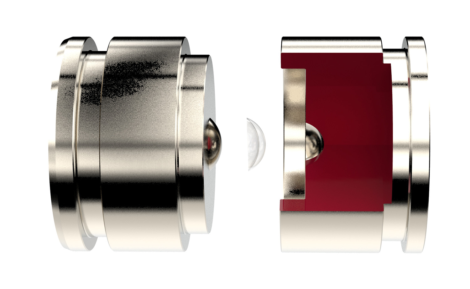
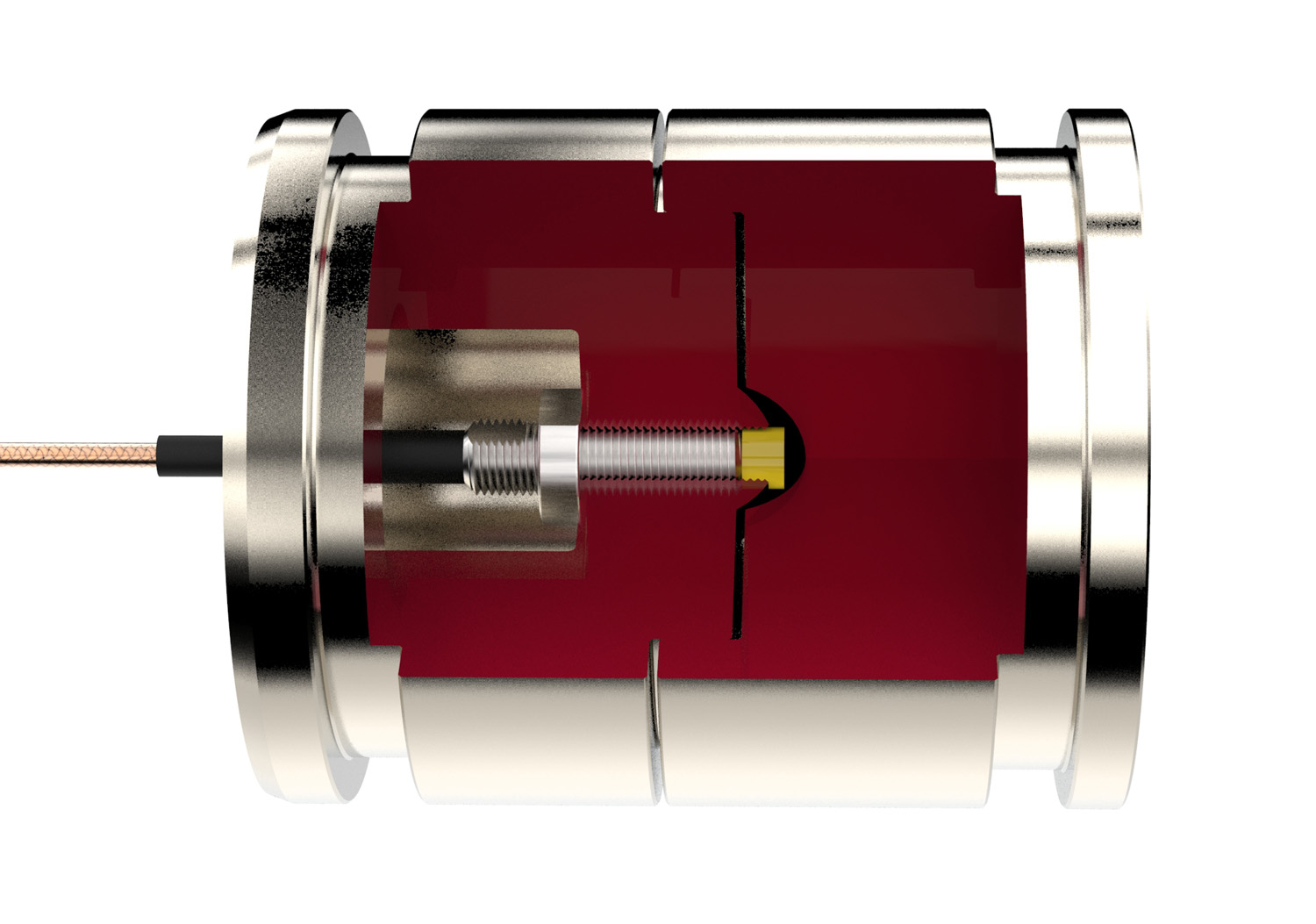
Oil-filled squeeze film damper (light red) and ceramic eddy current probes
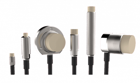
The used eddy current sensors of the CM series are miniature and additionally shielded against preattenuation by surrounding material (field focused design). The miniature probes do not require any additional cut-outs at the point of installation and can be installed directly and fully surrounded under pressure and high temperature. Conventional eddy current probes of similar size must be kept free of conductive materials around the head area of the probe. However, this would have negative effects on the hydrodynamic properties of the squeeze film damper. When using the eddylab probes of the CM series, these cut-outs can be completely avoided. We achieve this by using zirconium oxide ceramics as the housing material and field-focusing ferrite components for the construction of the measuring coil in the sensor head.

Installation comparison, left fully enclosed, right conventional with required cut-out.
The measurement is carried out on the test bench with a total of 8 sensors each with 2 pcs. for the axes in x- and y-direction in 4 different layers for complete recording of the shaft vibration and displacement. A further sensor is installed to determine the axial shaft displacement. The turbocharger is driven by a large air pressure tank which was previously filled with compressed air. The eddy current probes are used to determine the position of the turbo rotor at a speed of 300,000 rpm with accuracy of 1 micrometer.
During the operation of a milling spindle, there are deviations in the Z position which affect the machining accuracy of the workpiece. The spindle expands and shifts the Z point of the tool, mainly due to an increase in the temperature of the spindle during operation. If the spindle is operated at different speeds, a different lubricating gap thickness between the rolling elements and the running surface will occur in the bearing and the spindle will shift. Centrifugal forces have a minimal effect on the diameter and also influence the Z-position. These phenomena are called Spindle Growth. To minimize the deviation, a high-resolution eddy current sensor is mounted on the spindle nose near the tool fixture and measures the distance without contact.

Milling spindle with probe for compensating spindle growth (linear expansion)
If there is a change in length and an influence on the Z-position at the spindle nose, the output signal of the eddy current sensor changes. The signal is used in the machine control to compensate for spindle growth. The measuring system consists of an eddy current probe connected to analog or digital driver electronics. The AX driver electronics has an analog output and homogeneous metal and non-perforated surface is suitable for measuring with eddy current probes. The advantage of the analogue version is the small size of the driver and the possibility to install the electronics directly on or inside the spindle. Alternatively, the digital TX driver electronics can be used. This is also suitable for measurement on perforated object surfaces. The measuring range of the sensors is approx. 0.5 mm with a resolution of 50 nm and is unaffected by cooling lubricants. For special spindle designs, eddylab supplies customer-specific versions.
 Detailed view of eddy current probe (spindle expansion)
Silicone hydrogels are three-dimensionally crosslinked polymer chains of silicone with a high water content as solvent. These are used, for example, in the manufacture of soft contact lenses. The crosslinking gives the gel physical properties similar to water, but retains the shape like a solid. Silicone hydrogels offer high elasticity, good tear resistance and long life. In the manufacturing process, liquid base material is filled into the cavity of an injection mold. Irradiation with a UV-A light source triggers the crosslinking reaction and the silicone hydrogel solidifies. The mold opens and the finished parts are ejected. For economical production of such small parts, injection molds with many individual cavities, called mold nests, are used. Depending on the number of cavities, many parts are produced simultaneously in one injection process.
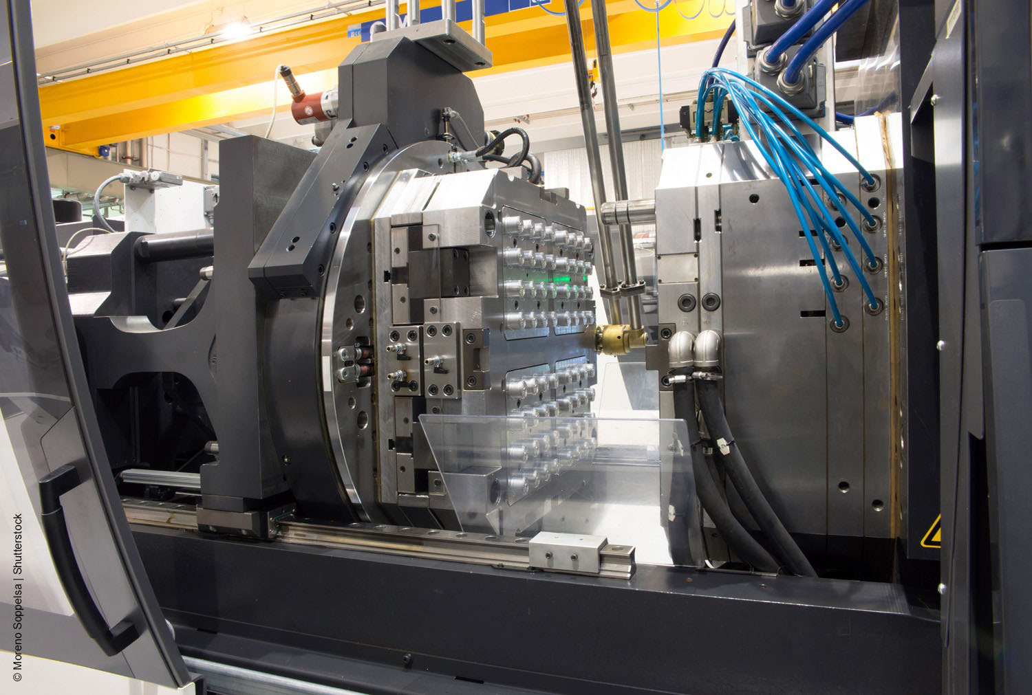 Injection mold with many individual cavities (mold cavities)
The shrinkage behavior of the material has a problematic effect on the end product. During the UV curing process, the material initially swells somewhat and then shrinks again. If the volume of the cavity remains constant, a small sink mark is created during the material shrinkage. Generally, these sink marks can be observed on any plastic injection molded part and usually occur at points of increased material thickness. In the case of conventional plastic parts, the visual disadvantages usually remain and these spots are hardly noticeable due to a structured surface. Precision parts, on the other hand, require a high degree of accuracy with regard to molding.
Integration of eddy current sensors for clamping gap control
The solution offers micrometer-accurate positioning of the closing gap between the mold halves. Eddy current sensors are integrated into the injection mold for this purpose. These are either installed at the edge of the mold halves or a few individual cavities are used as measuring cavities while the other cavities produce the product.
 Cavity for manufacturing the product
In the application example, the mold has 64 cavities. To integrate the eddy current sensors, the 4 cavities at the outermost corners are equipped with the eddy current sensors. They measure the remaining closing gap directly in the cavity.
 Cavity with eddy current sensor for closing gap measurement
In the production process, the mold closes and the silicone hydrogel is filled into the cavities. In the subsequent curing process, the mold is opened with micrometer precision to give the material a little more space. If the material in the cavities shrinks during curing, the mold is readjusted or completely closed exactly according to the shrinkage behavior. The eddy current sensors measure the distance between the two mold halves (nozzle and ejector side) without contact and supply the measurement data directly to the machine control system. Due to the micrometer-precise positioning of the mold halves relative to each other, the molding errors caused by shrinkage behavior are significantly reduced.