
With the discontinuation of the monolithic LVDT driver IC AD698APZ by Analog Devices, a key component for many analog LVDT conditioners is no longer available. This poses significant challenges for manufacturers and developers in maintaining existing systems and designing compatible new solutions. eddylab GmbH has addressed this problem through the complete in-house development of a digital LVDT conditioner. The DEEneo is microcontroller-based and replicates the functionality of the AD698, while also offering additional features such as linearization and temperature compensation. This article presents the technical foundations, development challenges and advantages of transitioning from analog to digital through a practical system design approach..
LVDTs (Linear Variable Differential Transformers) are inductive sensors used for precise position measurement, requiring a dedicated conditioner to function and generate an output signal. For many years, developers relied on universal monolithic LVDT driver ICs like the AD698 for signal conditioning. The development process was somewhat uncomplicated, as circuit design and layout were partially defined by the chip manufacturer. However, when such a component is discontinued - as in the case of the AD698 - developers are pushed to create powerful and compatible replacement solutions under tight deadlines.
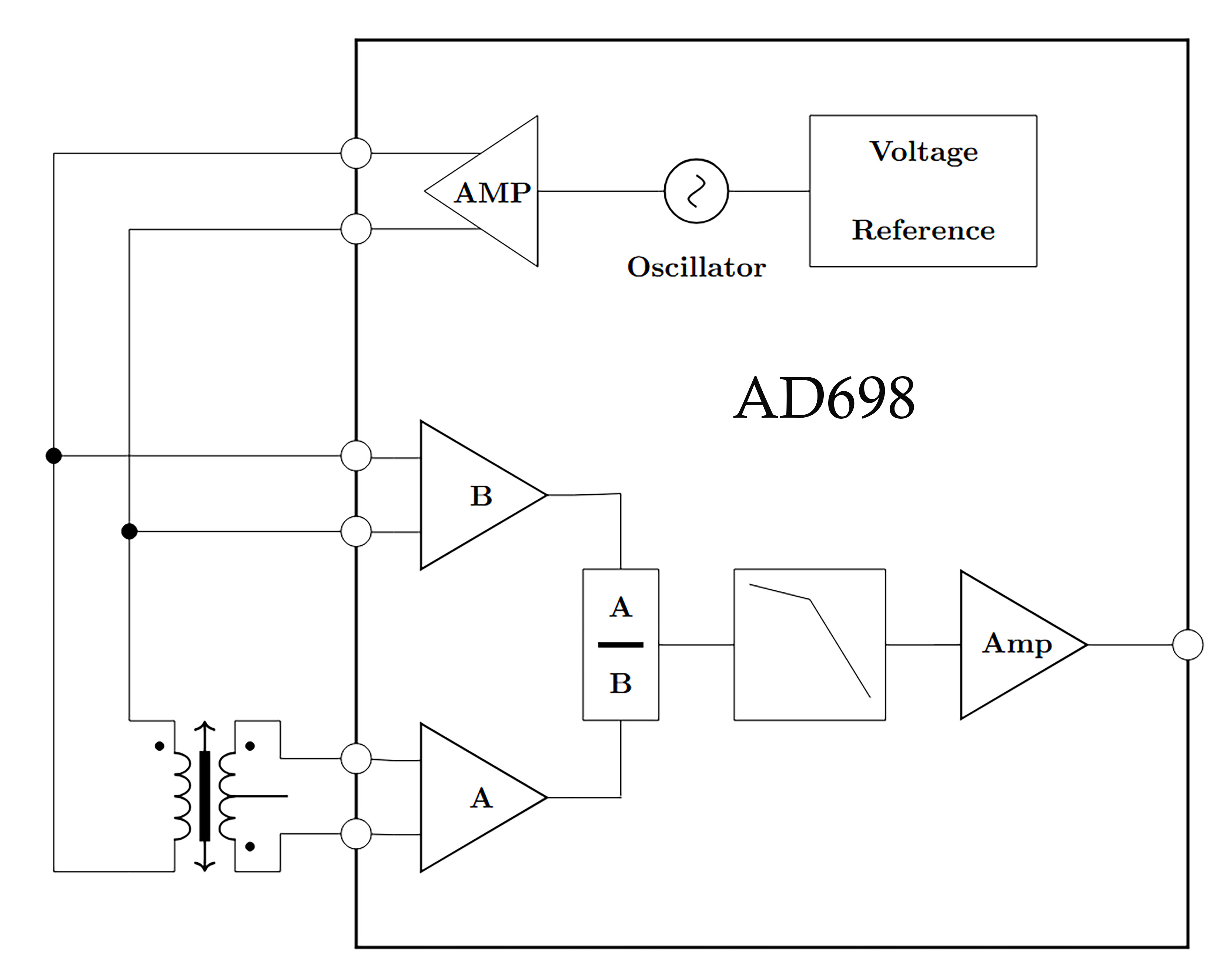 Fig. 1: Principle circuit diagram LVDT driver module AD698
The LVDT’s primary coil must be supplied with a sinusoidal voltage ranging from 1 to 5 volts at a frequency between 1 and 20 kHz, as defined by the LVDT sensor manufacturer. These values are critical for achieving optimal linearity and sensitivity. Inaccurate supply voltages or frequencies degrade sensor performance. If the primary voltage is too low, the signal-to-noise ratio resolution of the sensor reduces. On the other hand, too high voltage may cause saturation, self-heating, or even audible whistling of the core due to magnetostrictive effects.
An incorrect excitation frequency significantly impairs linearity, sensitivity, and noise performance. For instance, if a sensor is supplied with the wrong frequency, the linearity can suffer significantly and therefore be far outside the sensor specification. Furthermore, the transmission ratio of the sensor is frequency-dependent, so if the wrong frequency is selected, the sensitivity decreases and consequently the output noise increases. The resolution of the sensor would therefore be poor. However, if the sensor is supplied with the correct voltage and frequency, this is not enough.
Hence, LVDT conditioners must generate a distortion-free, stable, and temperature-independent sine wave to power the primary coil. Since the LVDT operates as a transformer, any disturbance in the excitation directly affects the secondary signal, degrading overall system accuracy. This requires a precise voltage and frequency-stabilized signal generator to supply the primary coil. The AD698 achieved this through an oscillator controlled by a precise reference voltage.
The AD698 also performs demodulation of the secondary voltage and calculates a ratiometric measurement between secondary and primary signals (A/B), considering both phase and amplitude. This approach enhances noise immunity, as interference present in both signals is largely canceled out. Making LVDT systems well-suited for harsh environments with long cable lengths between sensor and LVDT conditioner.
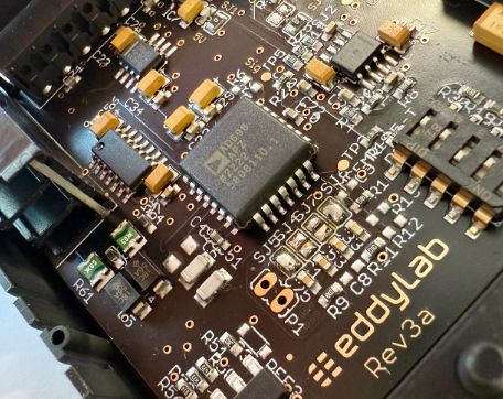 Fig. 2 :Example of LVDT electronics using the AD698
Post-demodulation, the signal undergoes additional processing and filtering, including active multi-pole low-pass filtering to decouple it from the excitation frequency. For example, a 6th-order Butterworth filter with a 500 Hz cutoff may be applied to a 5 kHz excitation, offering ~120 dB attenuation per decade to suppress interference. This corresponds to a signal attenuation by a factor of 1 million for every tenfold increase in frequency above the cut-off frequency.
After filtering the output is then conditioned to standard formats such as unipolar or bipolar voltage output 0…10 V, 0…5 V ±10 V, ±5 V or current output 0…20 mA, 4…20 mA.
The AD698 provided developers with a stable and relatively simple solution. Key design tasks involved building a low-noise bipolar power supply, buffering the primary excitation to minimize heating and ensuring EMC compliance. Gain and phase adjustments were typically made using DIP switches or potentiometers. Additional requirements such as EMC, short-circuit protection, and cable break detection were also manageable. Crucially, developers did not need to address temperature effects or the finer points of signal processing, the AD698 handled these internally.
For matching the LVDT and AD698, measures for phase compensation and gain adjustment via DIP switches or potentiometers are necessary to put the AD698 at the correct operating mode as well as the integration of EMC protection, reverse polarity and short circuit protection and cable break detection. This are simple things for developers and little thought is lost on how to set up high-performance demodulation or how to get the temperature coefficient of the LVDT under control.
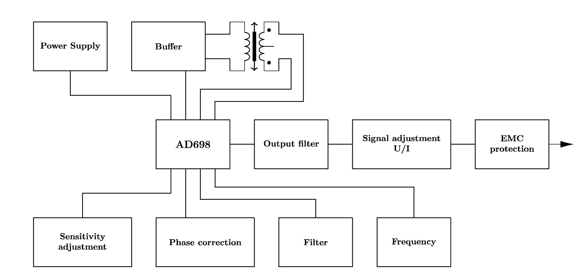
Fig. 3: Schematic diagram of the analog LVDT electronics IMCA using the AD698
When a design depends on a specific IC, its discontinuation impacts the entire system architecture. This occurred with the AD698 in 2023. While residual stock remains, prices have surged and availability is unpredictable, often relegated to brokers who capitalize on the shortage. The time available to develop a fully compatible replacement is limited, creating urgency for alternative solutions.
eddylab GmbH, based in Otterfing, anticipated this scenario. According to Managing Director Michael Reiter:
„We, too, used the AD698 for over 20 years, but I always feared it would be discontinued. That’s why we began in-house development early. Now the chip is indeed obsolete, we’re prepared with a successor.“
eddylab identified the problem at an early stage and the DEEneo was developed independently of any universal IC and is built on a microcontroller platform, leveraging eddylab’s experience with microcontroller-based eddy current sensors. However, the challenges in developing a digital replacement were substantial, particularly in designing a robust demodulation algorithm - the core of any LVDT signal processing system.
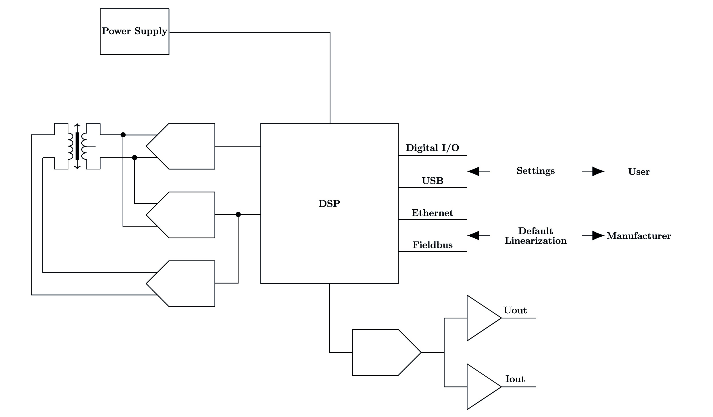
Fig. 4: Digital LVDT electronics DEEneo using a microcontroller
Developing DEEneo required precision in both hardware and firmware design. The electronics needed to supply a low-noise, high-resolution, distortion-free output while minimizing microcontroller-induced interference. This demanded a complex PCB layout, with isolated ground planes for analog and digital domains, and stable precision reference voltages.
Power supply decoupling was also essential to prevent digital switching noise from coupling into analog circuitry.
To meet stringent metrological standards, internal ADCs and DACs were insufficient. Instead, external converters with ≥16-bit resolution and integrated filtering were used. Microcontroller-generated clock signals often produce measurable noise on I/O pins, complicating signal stability.
The LSB (Least Significant Bit) issue - jitter in the final digit of a digital output - can resemble a fluctuating reading - comparable to a digital display on a bathroom scale and the disruptive jumping back and forth of the last digit of the display. As a result, microcontrollers rarely offer DACs beyond 14-bit resolution. Using external converters with high resolution increases the complexity of the design, as in addition to the communication interfaces, such as I²C or SPI, the physical integration into the system and the management in the firmware must also be taken into account.
High-resolution external converters increase complexity but ensure superior noise performance and enable advanced features like active temperature compensation.
These requirements inevitably lengthened development time and increased system cost. However, the benefits of higher resolution, improved noise performance, and easier calibration justify the effort.
All of this leads to longer development times and higher system costs. However, the effort pays off and benefits of increased system resolution, improved noise behavior and temperature compensation can be achieved with digital LVDT conditioners. The customer also feels the advantages and adjusting the setup of the system becomes very simple and convenient.
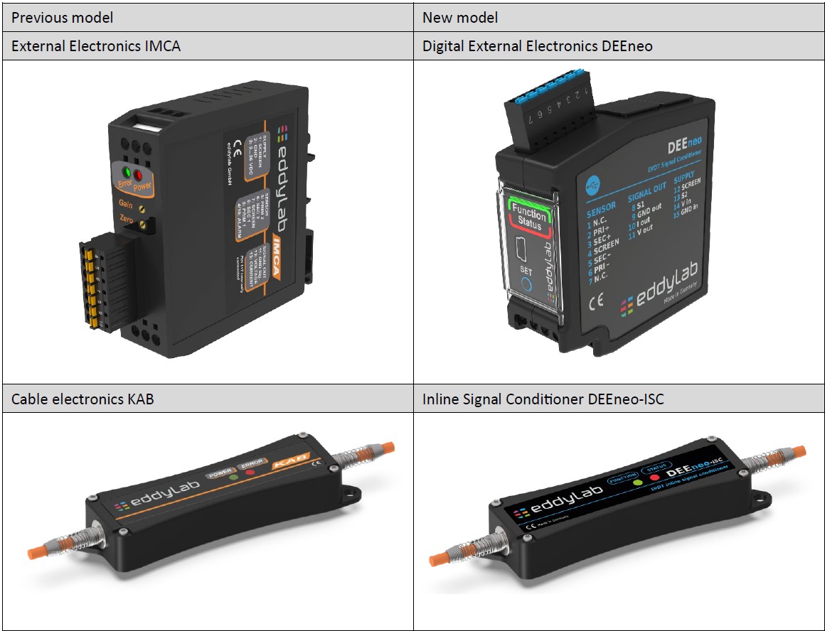
Fig. 5: Compare analog (left) vs. digital LVDT electronics (right)
Once technical hurdles are addressed and a high-resolution signal is achieved, digital LVDT conditioners offer multiple advantages such as simplified LVDT sensor and LVDT conditioner matching, automated calibration routines and embedded certificate generation.
Unlike analog systems based on the AD698 which required manual configuration via DIP switches or component changes, the LVDT conditioner DEEneo allows all settings to be adjusted via software tools or integrated hardware buttons. For instance, calibration involves positioning the ferromagnetic core of the LVDT at each end of its travel and pressing the SET button – that’s it. The analog output signal is available straight, correctly scaled to the desired measuring range
Author: Michael Reiter, eddylab GmbH, 04/2025